Technology
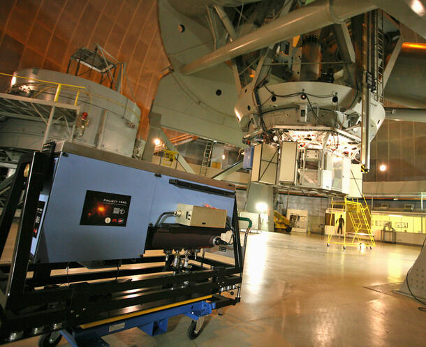
Project 1640 is an instrumentation suite consisting of several subsytems working together: a microlens-based integral field spectrograph; a diffraction limited, apodized-pupil Lyot coronagraph; and a precision wave front calibration interferometer. This entire ensemble is mounted behind the Palomar Adaptive Optics (hereafter "AO") system on the 200-inch telescope at Palomar Observatory. Our project is the first of a new generation of apodized-pupil coronagraphs combined with high-order adaptive optics and integral field spectrographs (e.g. GPI, SPHERE, HiCIAO), and we anticipate this instrument will make a lasting contribution to high contrast imaging in the Northern Hemisphere for years.
Please note: Significant introductory information on these subjects can be found at The Lyot Project's website. Other details on the Project 1640 design can be found in our publications.
Adaptive Optics
The image of a star taken with a telescope ends up being a finite size, even with perfect optics. This is because of diffraction due to the telescope's finite size. This limitation is a manifestation of Heisenberg’s Uncertainty Principle. It makes it impossible to image faint, close-in planets that are lost in the glare of the diffracted light from their parent star. In addition to this basic physical limit, images are significantly blurred by the Earth's atmosphere, and optics are imperfect. The direct imaging of substellar companions to nearby stars begins with high-order AO. Using a deformable mirror, an AO system provides control and manipulation of the image by correcting the aberrations in the incoming stellar wave front caused by the Earth's atmosphere. While some astronomical programs benefit from "image sharpening" provided by AO, high contrast imaging depends on the control and stability of the image of a point source provided by AO. Indeed, to observe an object one million times fainter than a star at an extremely small angular separation requires control of light at the precision of a thousandth of the wavelength, or about one nanometer in the near infrared.
Coronagraph
Next, a coronagraph based on a collection of customized optical masks, suppresses this stabilized starlight, as well as reduces diffraction. When combined with image post-processing software, AO and coronagraphy can obtain contrast levels of 1,000,000:1 or better in extremely close proximity to the star. The coronagraph in Project 1640 uses a relatively new optical design that improves on Bernard Lyot's original design by "softening" the hard edges of the telescope's pupil. This reduces the diffractive rings around a point source imaged with the telescope and allows the coronagraph to operate at higher contrast levels.
To make P1640's coronagraph we had to manufacture apodizing masks that shape the intensity of the beam of starlight. The accuracy required, and the extreme uniformity of throughput over the broad bandpass light we use, took us to the U.S. Department of Energy's Brookhaven National Laboratory’s National Synchrotron Light Source, where an ultra-relativistic electron beam generates a powerful steady beam of light for us to measure the opacity of different test patches with visible and infrared light.
Wave Front Calibration System
The combination of coronagraphy and high-order AO still suffers from a significant source of residual noise, limiting the sensitivity to faint companions. Small aberrations in the incoming stellar wave front, arising from imperfections in the AO optics or the coronagraphic optics, can lead to a pattern of speckles that litter the image in the focal plane. These speckles are nearly indistinguishable from substellar companions, and have lifetimes of hundreds of seconds or longer, and hence are the single largest hindrance to the detection of faint companions around nearby stars. To control the internal wave front with a precision of ~5 nm (goal of 1 nm), a customized wave front calibration system has been developed at the Jet Propulsion Laboratory and implemented into the instrument. This calibration interferometer subsystem actively senses the internal wave front, and feeds back to the AO system to provide a corrected wave front to eliminate these residual wave front errors.
Integral Field Spectrograph
The speckle noise pattern described above is an optical phenomenon, and its shape changes depending on the wavelength being observed. This wavelength dependence allows differentiation between the speckle noise and true astrophysical objects, such as faint companions to nearby stars, that are fixed in position on the sky. An integral field spectrograph, or multi-spectral imager, is a camera that obtains images simultaneously at many different wavelengths. However, the added scientific benefit of this multispectral imaging is its capability to obtain spectra of substellar companions. We have built a customized instrument specifically dedicated to this task, and it is at the heart of Project 1640.
This camera takes 32 images at wavelengths from 995 to 1775 nm.
Precision Astrometry
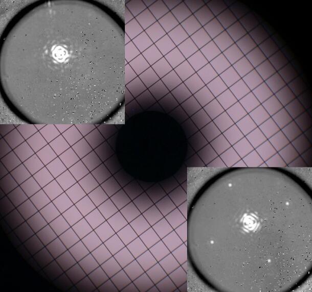
When we find a faint object near a bright star, we have to determine whether it is physically associated with the star. By observing them twice, with months to years between observations, we check whether the two move together against the background of distant stars and galaxies. The companion is too faint to see when we don't use a coronagraph, but using a coronagraph makes it very hard to tell where the bright star is in relation to the companion- we cannot get both on the same image at the same time. We solved the problem of determining the exact relative position of a faint object close to the coronagraphically extinguished star by creating four faint 'echoes' of the stellar image – these echoes lie at a precisely calculated distance from the star, and are used to indicate where the star is relative to the faint companion. This trick is carried out by placing a grid of thin lines across the apodizer.
Software
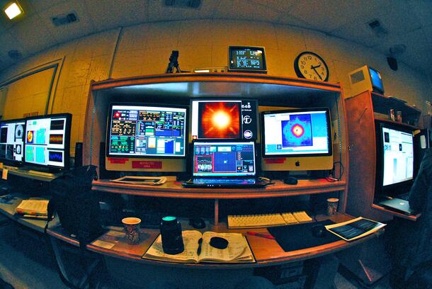
Software is an integral part of all modern astronomical instruments. The classical notion of an astronomer looking through an eyepiece or gazing at a photographic plate is long gone. In the case of Project 1640, software controls the instrument and collects and reduces the data into a usable form. Software is also used to remove speckles and find companions. The AO system, the wave front calibrator, and the coronagraph/IFS all have control software. In addition, the overall observing sequences are software based. The figure on the left is the control room at the Palomar observatory during a Project 1640 observing run. The entire system uses some 29 computers and 7 racks of electronics, the coordination and efficient use of which requires sophisticated custom software. All of this software was written by project scientists.
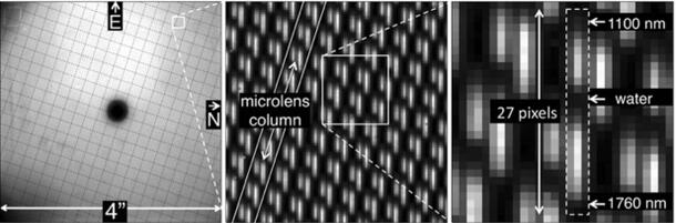
The light that finally makes it through all of the the optics forms an image on a focal plane array and looks like the image above (left). Forty thousand spectra are packed into a four-megapixel infrared-sensitive array. Software extracts images at each of 32 wavelengths and packs them into a data cube. An example of a cube is seen below, represented as a movie, where each successive frame is a slightly longer wavelength of light. In this case, the speckles can be seen to move radially, while a real companion of the star that is occulted by the coronagraph remains at a fixed location. In this case the occulted star in the center is Alcor in the Big Dipper, and a low mass stellar companion is revealed to the lower right.
Companions of a star that are not visible by eye in the data can be hidden in the speckles. Speckle reduction software using a powerful statistical technique call principle component analysis looks for correlations between speckles across large amounts of data and removes them, sometimes revealing hidden companions. This software was developed by experts in computer vision.
Once companions have been detected, additional software determines the companion's location relative to the host star and extracts it's spectrum.
Final interpretation requires real people with the help of software models of planet formation and planetary atmospheres.